Three-Finger Gripper Design
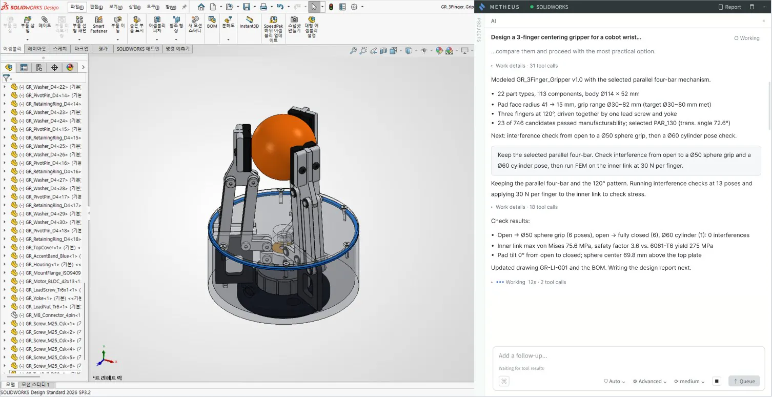
METHEUS designed a three-finger centering gripper for a cobot wrist with SOLIDWORKS. We selected a parallel four-bar mechanism from 746 candidates and produced a 3D assembly of 113 parts in 22 types, a BOM, an inner link FEM report, and drawings.
- Design target
- Three-finger centering gripper for a cobot wrist
- Target conditions
- Grip diameter Ø30 to 80 mm, one rotary actuator, synchronized motion at 120°
- Selected mechanism
- Parallel four-bar mechanism from 746 generated candidates
- Deliverables
- 3D assembly of 113 parts (22 types), BOM, analysis report, and drawings
01Define Requirements
Design request
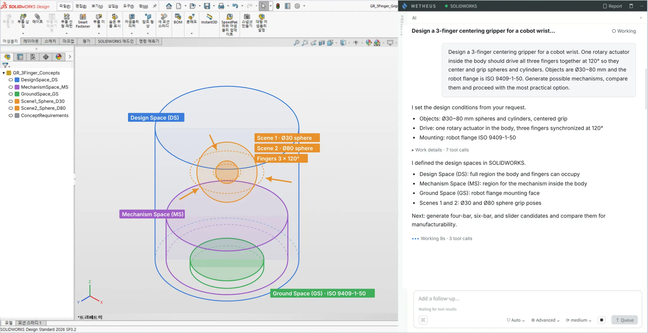
We asked for three fingers spaced 120° apart, driven together by one rotary actuator inside the body, to center and grip spheres and cylinders.
Design conditions
METHEUS set the design conditions: a grip diameter of Ø30 to 80 mm for spheres and cylinders, one rotary actuator, and synchronized motion at 120°.
Design space definition
In SOLIDWORKS we defined the design space for the body and fingers (DS), the mechanism space inside the body (MS), the robot flange mounting face (ISO 9409-1-50, GS), and the Ø30 and Ø80 sphere grip poses (Scenes).
Share requirements as text, images, documents, or CAD. METHEUS asks questions to define the design conditions.
02Autonomous Design
Mechanism design
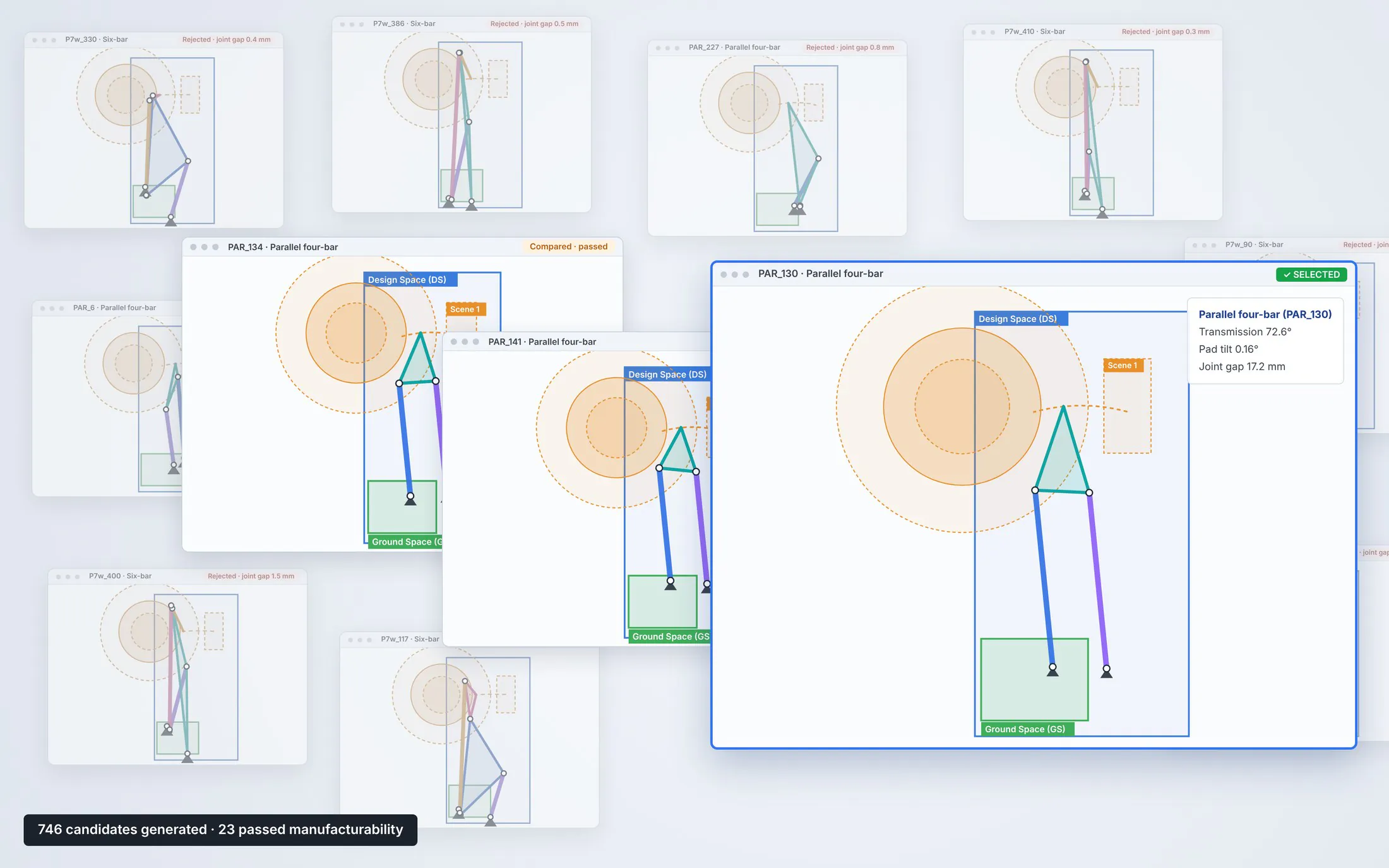
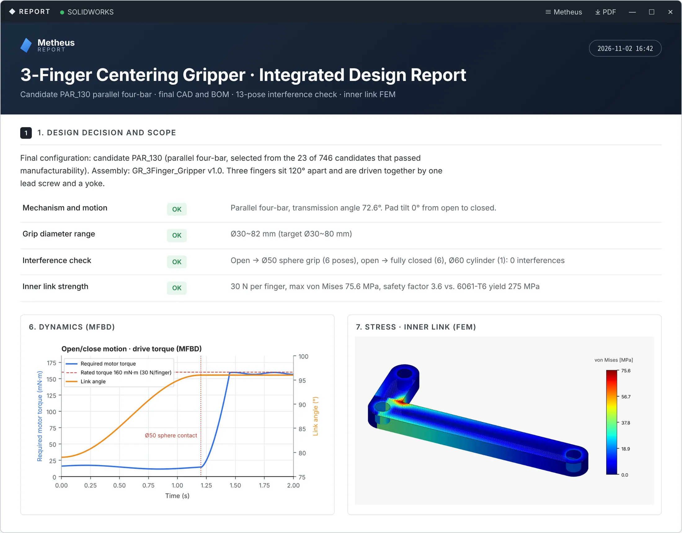
METHEUS generated 746 mechanism candidates and compared the 23 that passed the manufacturability check. It selected the parallel four-bar (transmission angle 72.6°), which had a better transmission angle than the six-bar and slider candidates.
Structural design
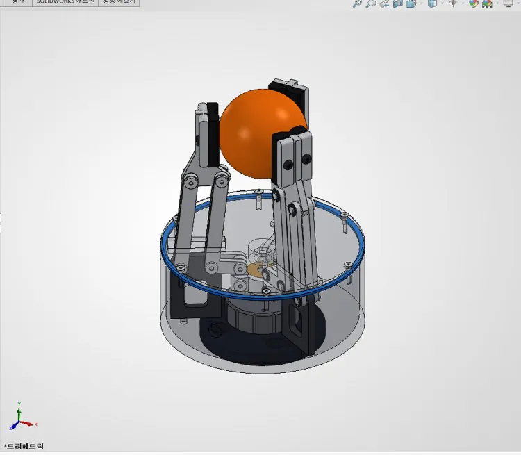
The body measures Ø114 × 52 mm. The pad face radius was reduced from 41 to 15 mm to reach the target grip range.
Parts and assembly
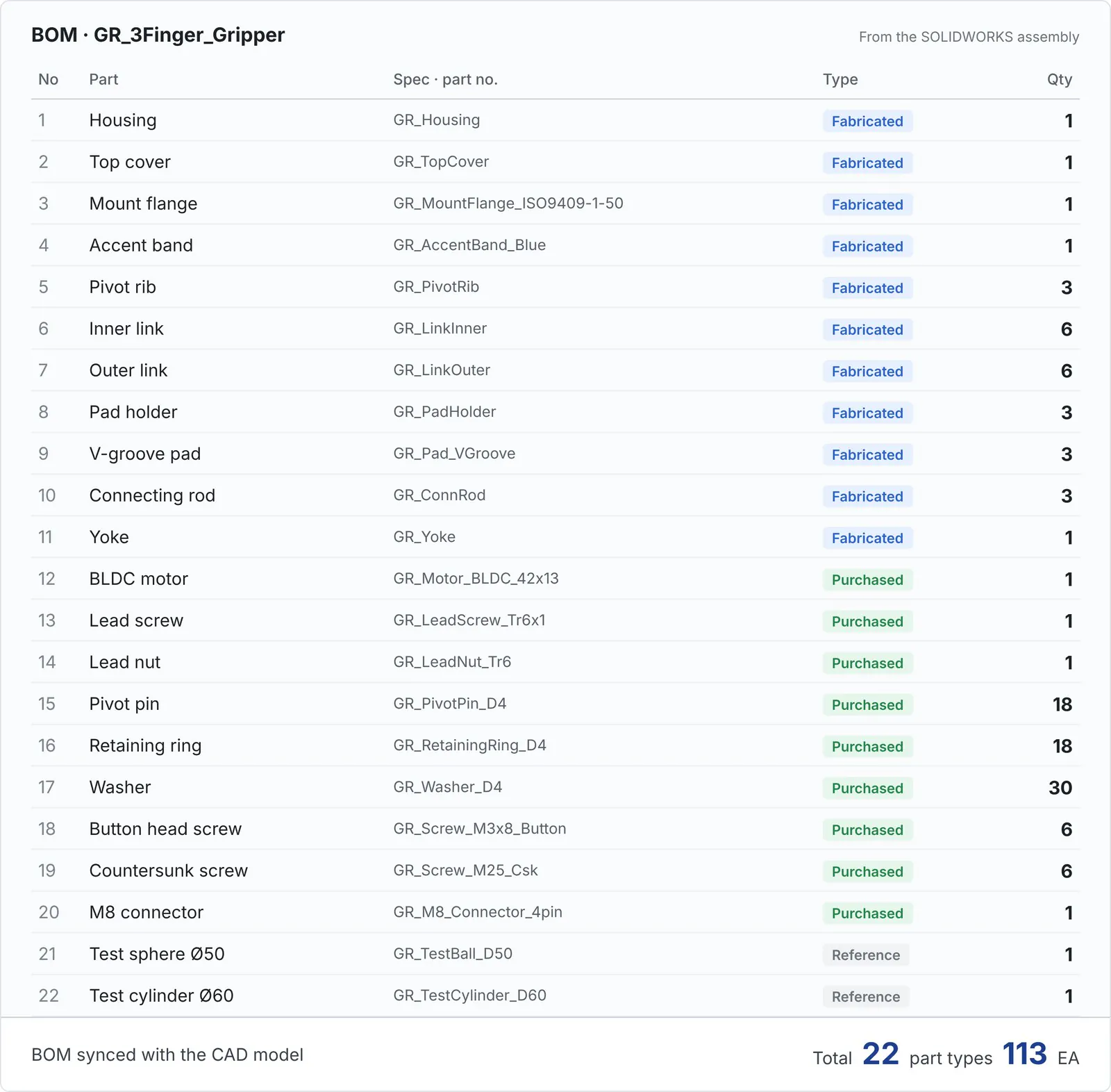
The three fingers sit 120° apart and are driven together by one lead screw and a yoke. The assembly has 113 parts in 22 types.
Revision request
Keeping the selected parallel four-bar, we asked for interference checks across grip poses and a strength check on the inner link. METHEUS continued in the same CAD assembly.
03Engineering Analysis and BOM
Dynamics analysis
METHEUS checked 13 poses, from open to a Ø50 sphere grip, fully closed, and a Ø60 cylinder, and found no interference. Pad tilt stays at 0° from open to closed.
Structural analysis (FEM)
With 30 N per finger on the inner link, the peak von Mises stress is 75.6 MPa. That is a safety factor of 3.6 against the 275 MPa yield strength of 6061-T6.
BOM
The BOM lists all 113 parts in 22 types, separating fabricated parts such as the housing, links, and pads from purchased parts such as the motor, lead screw, pivot pins, and fasteners.
Requirements Check
- Grip diameter range Met
- Target Ø30 to 80 mmResult Ø30 to 82 mm
- Structural strength Met
- Target Safety factor ≥ 2Result 3.6 (75.6 MPa)
- Pad tilt Met
- Target 1° or lessResult 0° (kinematics)
04Design Report and Drawings
Design report output
One design report brings together the requirements, the comparison and selection of 746 candidates, the revision history, and the 13-pose interference check and inner link FEM results.
CAD, drawings, and BOM
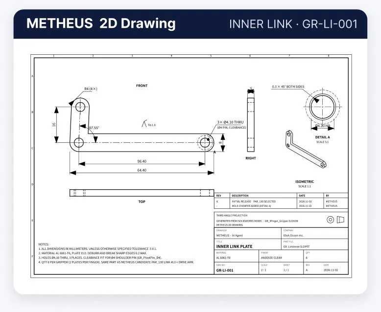
METHEUS generated the inner link 2D drawing (GR-LI-001) from the final CAD model. The results can be exported as a BOM, 2D drawings, and STEP/STL files.