Flip Transfer Station Design
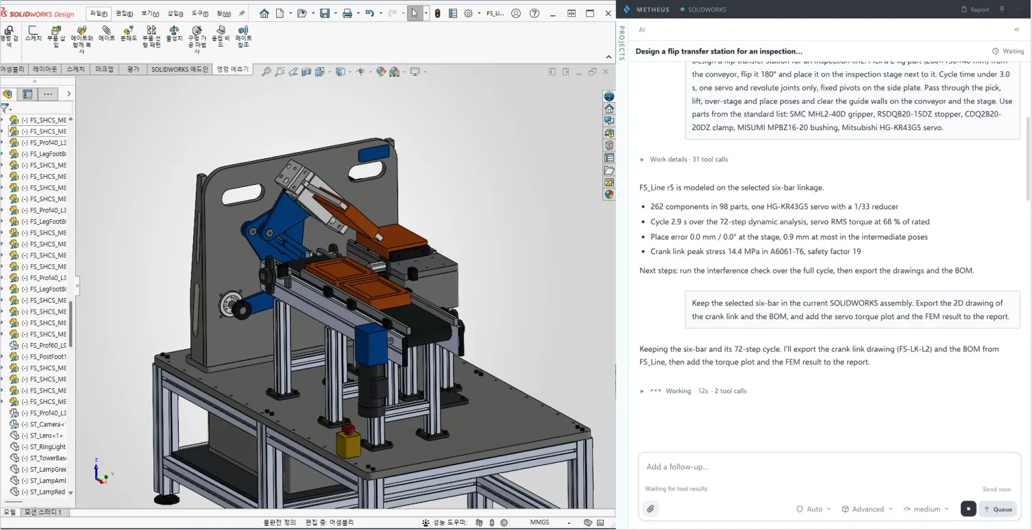
METHEUS designed a station with SOLIDWORKS that flips parts 180° from a conveyor onto an inspection stage. We selected a six-bar linkage from more than 1,000 candidates and produced a 3D assembly of 262 parts in 98 types, a BOM, a servo torque and link stress report, and drawings.
- Design target
- Part flip transfer station for an inspection line
- Target conditions
- 180° flip of a 2 kg part, cycle time of 3.0 s or less, one servo motor
- Selected mechanism
- Six-bar linkage from 1,000+ generated candidates
- Deliverables
- 3D assembly of 262 parts (98 types), BOM, analysis report, and drawings
01Define Requirements
Design request
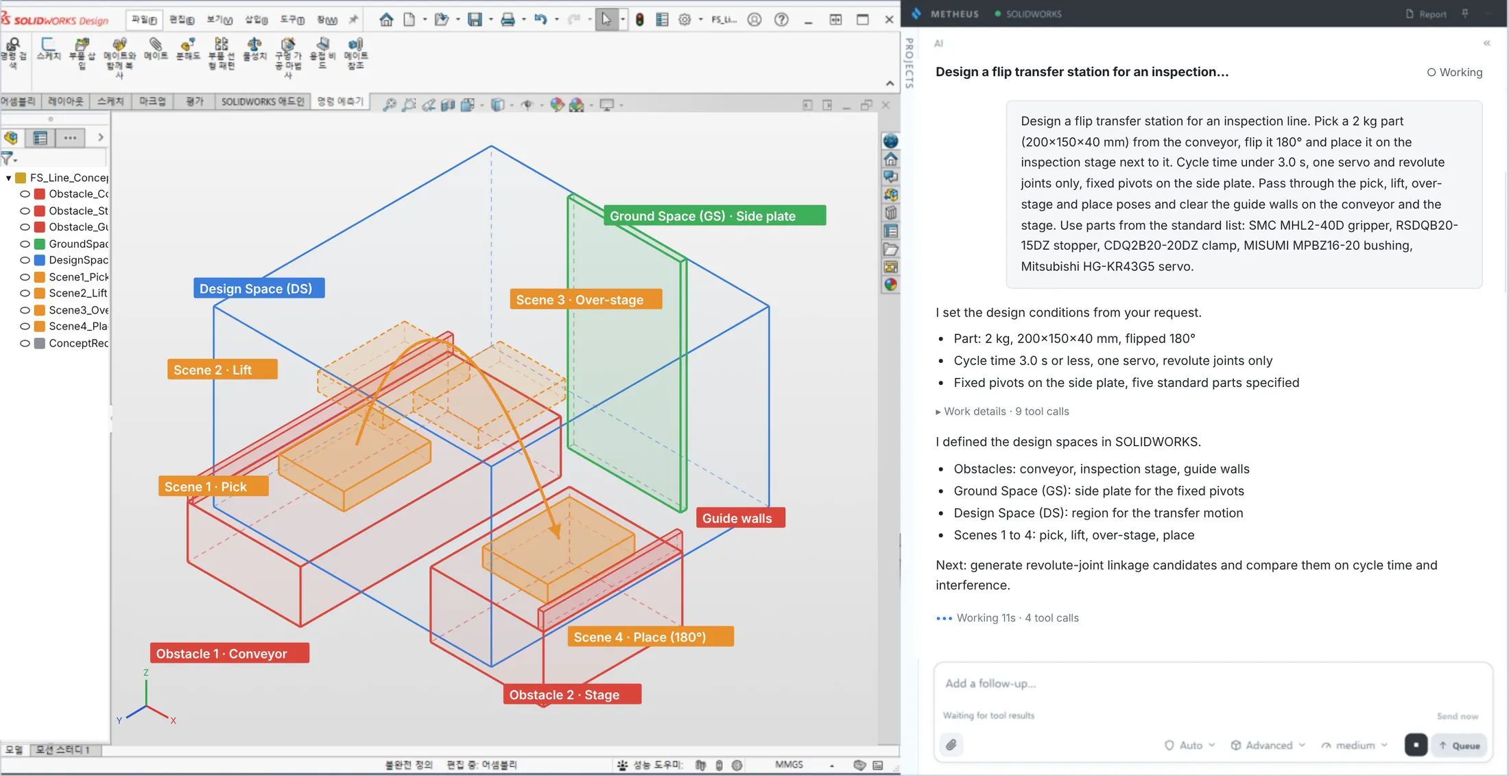
We asked for a station that grips a 2 kg part (200 × 150 × 40 mm) on the conveyor, flips it 180°, and places it on the inspection stage next to it.
Design conditions
METHEUS set the conditions: a cycle time of 3.0 s or less, one servo motor, revolute joints only, and fixed pivots on the side plate.
Design space and transfer path
We defined the conveyor, inspection stage, and guide walls as obstacles and the side plate as the fixed pivot face (GS), and set four poses (Scenes): pick, lift, over-stage, and place.
Standard parts list
We specified an SMC MHL2-40D gripper, RSDQB20-15DZ stopper, CDQ2B20-20DZ clamp, MISUMI MPBZ16-20 bushing, and Mitsubishi HG-KR43G5 servo.
Share requirements as text, images, documents, or CAD. METHEUS asks questions to define the design conditions.
02Autonomous Design
Mechanism design
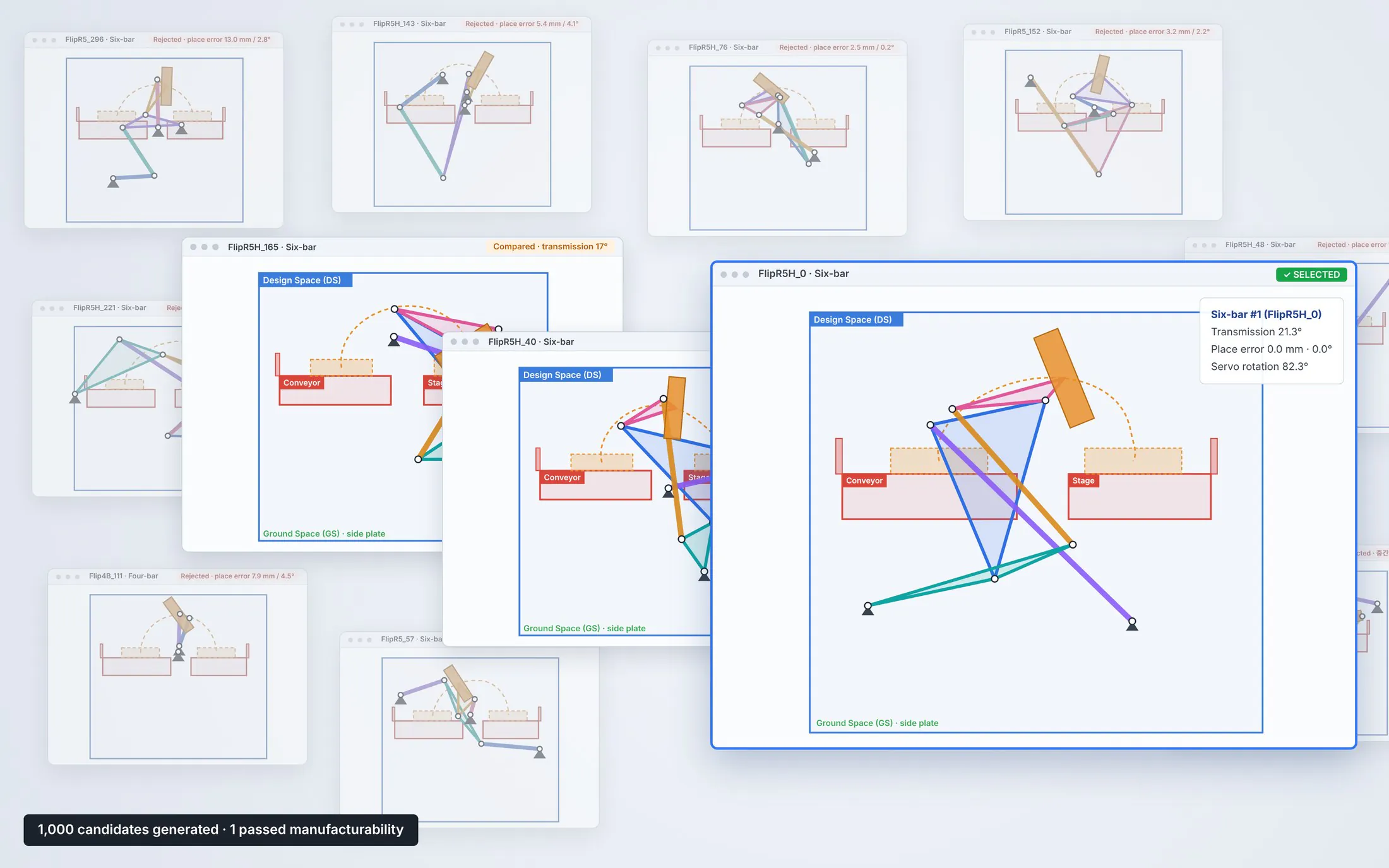
METHEUS generated and compared more than 1,000 mechanism candidates and selected six-bar #1 (transmission angle 21.3°). Six-bars #165 and #40 were reviewed as alternatives.
Parts and assembly
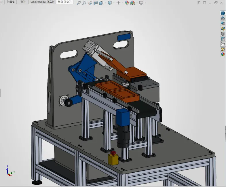
The station was modeled on the selected six-bar and driven by one HG-KR43G5 servo with a 1/33 reducer. With the specified standard parts, the assembly has 262 parts in 98 types.
Revision request
Keeping the selected six-bar, we asked for the crank link drawing and the BOM, and for the servo torque plot and FEM result to be added to the report.
03Engineering Analysis and BOM
Dynamics analysis
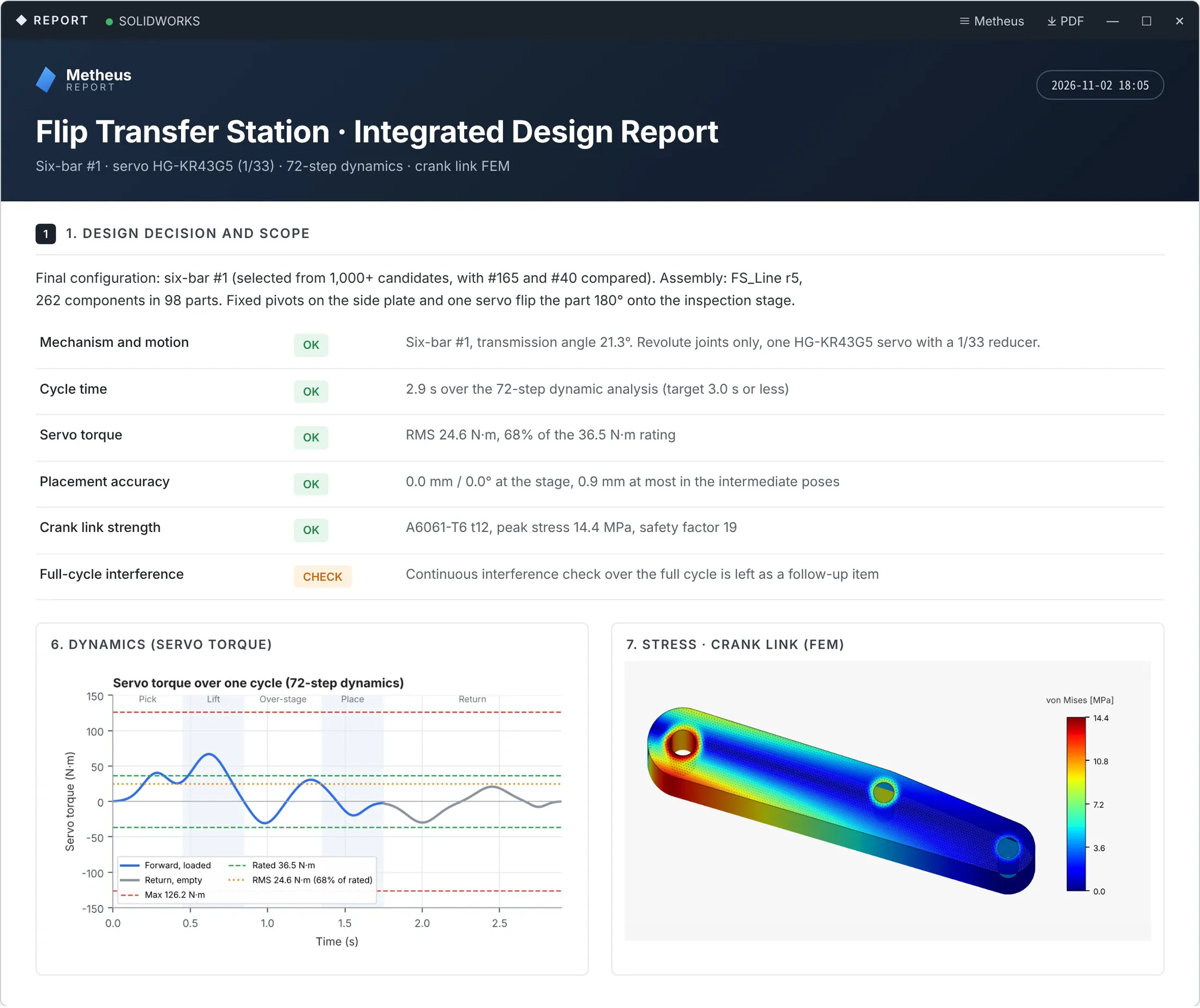
A 72-step dynamic analysis confirmed that one cycle takes 2.9 s. Servo RMS torque is 68% of rated.
Placement accuracy
Placement error at the inspection stage is 0.0 mm and 0.0°, and stays within 0.9 mm in the intermediate poses.
Structural analysis (FEM)
The crank link (A6061-T6) peaks at 14.4 MPa, a safety factor of 19.
BOM
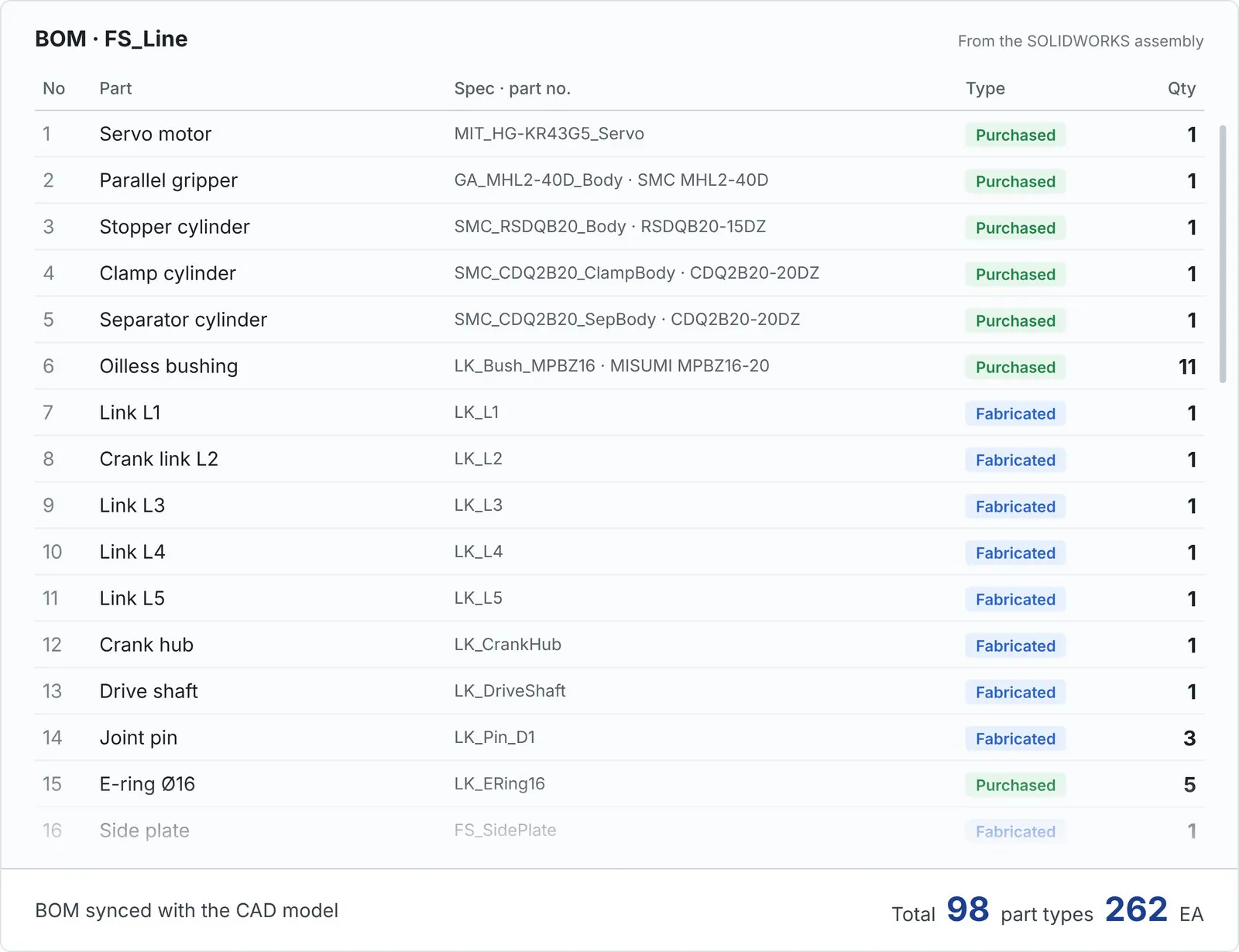
The BOM lists 262 parts in 98 types, separating purchased parts such as the servo, gripper, and bushings from fabricated parts such as the links, hub, and plates.
Requirements Check
- Cycle time Met
- Target 3.0 s or lessResult 2.9 s
- Structural strength Met
- Target Safety factor ≥ 2Result 19 (14.4 MPa)
- Placement accuracy Met
- Target Within ±1 mmResult 0.0 mm · 0.0°
04Design Report and Drawings
Design report output
One design report brings together the requirements, the candidate comparison and selection rationale, the revision history, the 72-step dynamics and crank link FEM results, and the remaining check (full-cycle interference).
CAD, drawings, and BOM
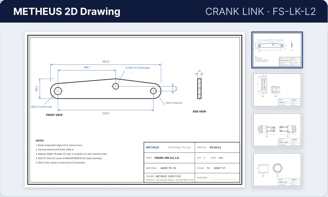
METHEUS generated the crank link 2D drawing (FS-LK-L2) from the final CAD model. The results can be exported as a BOM, 2D drawings, and 3D CAD files.