Bus Folding Door Design
METHEUS took a bus folding door from mechanism exploration through 3D modeling, analysis, and a design report. The new linkage accounts for limited vehicle space and passenger clearance.
- Design target
- Bus passenger folding door
- Target conditions
- 880 mm doorway, clear opening of 750 mm or more, 2 to 3 s to open and close
- Selected mechanism
- Dual rotary three-link folding mechanism from 150 generated candidates
- Deliverables
- Detailed 3D model, BOM, dynamic analysis, integrated report
01Design Problem Input
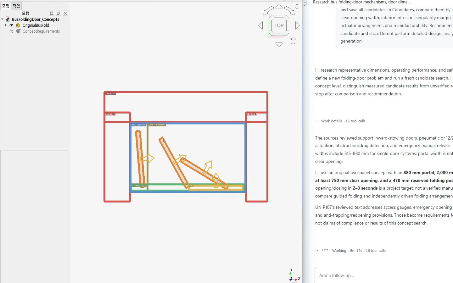
Target motion definition
We set a target of at least 750 mm of clear opening within an 880 mm doorway, with the door folding smoothly from closed to fully open.
Space constraint definition
We checked clearance from the body, steps, and handrails, plus interior protrusion and the motion path.
Other condition input
We used door size, opening time, emergency release, and anti-pinch requirements as references. We asked for a new linkage suited to sheet-metal fabrication and welding, using standard parts where possible.
In Design Problem Input, you can set every value precisely, and you can also edit values directly and easily in the CAD sketch.
02Autonomous Design

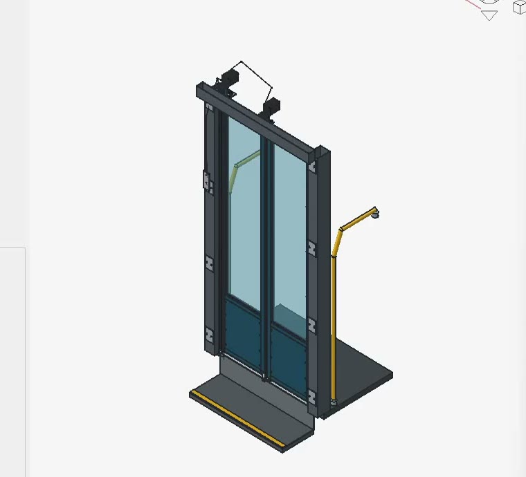
Mechanism generation
METHEUS generated linkages for the opening and clearance requirements. We compared their paths, singularity margins, joint counts, actuator layouts, and manufacturability.
Design review
We played each door motion, checked panel collisions, body interference, passenger-space intrusion, and actuator layout, then selected a candidate for detailed design.
3D modeling and part selection
We built a 3D model of the selected mechanism with door panels, links, mounts, an actuator, stoppers, and an emergency release, using standard parts where possible.
Part assembly and detailed design
We checked the full door motion, corrected collisions and interference, and reviewed seal contact, stoppers, emergency release, and assembly.
BOM and drawings
We separated purchased and fabricated parts in the BOM and documented the final CAD model and door motion.
03Engineering Analysis and Reports
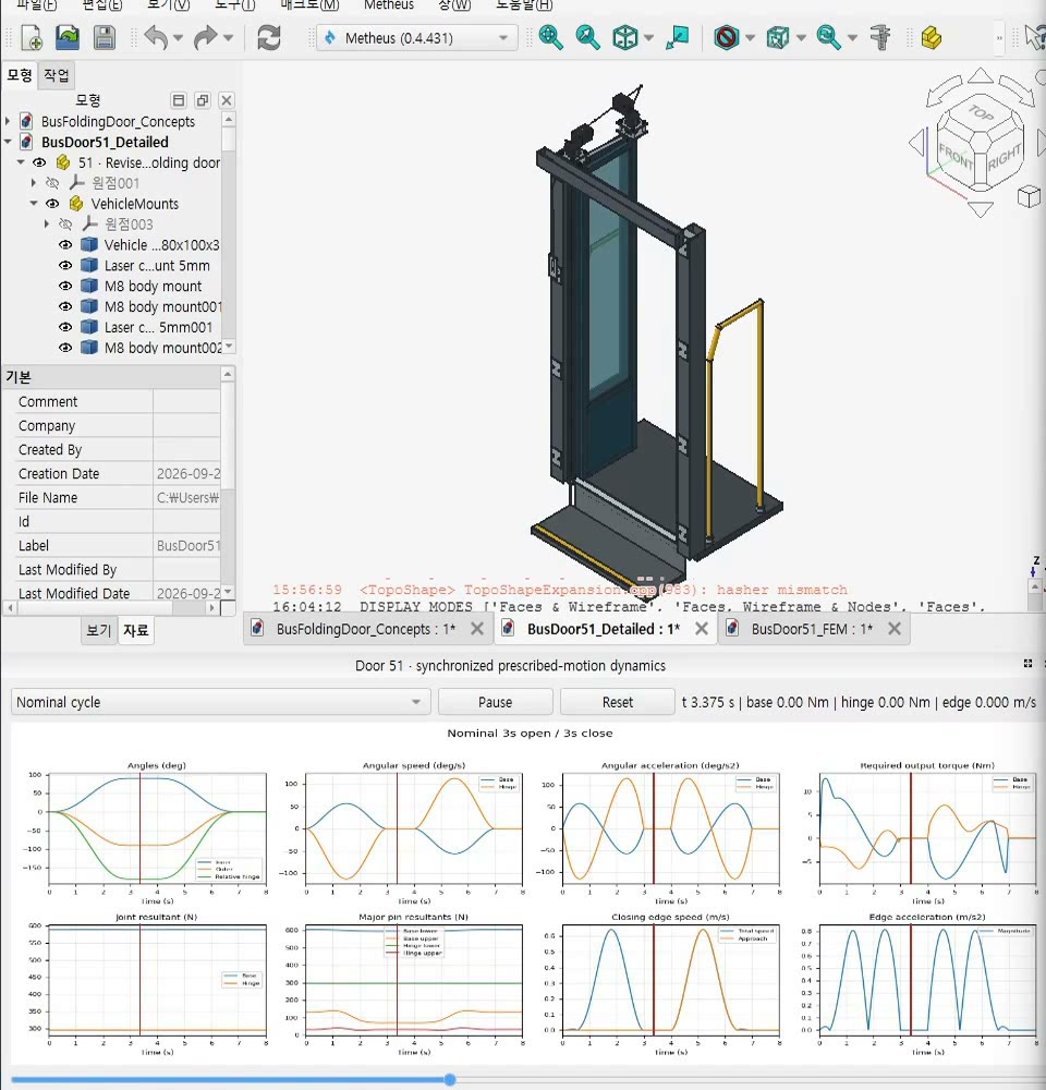
Analysis setup and execution
With material, contact, mounting, weight, and drive loads applied, we checked drive force, pin reactions, peak stress, and displacement at key door positions.
Motion analysis and design report output
A full-cycle dynamics study checked forces, reactions, and door speed. Candidate comparisons, detailed design, and analysis were compiled in one design report.