Robotic Gripper Design
One design prompt and one revision request produced a two-finger robotic gripper. We chose a four-bar mechanism and created a 97-part BOM, drawings, and finger FEM results.
- Design target
- Two-finger gripper mounted on a robot wrist
- Input
- One 54-word English prompt, one revision request
- Selected mechanism
- Four-bar RRRR mechanism from 300 generated candidates
- Deliverables
- 97-part BOM and drawings, finger FEM analysis report
01Design Problem Input
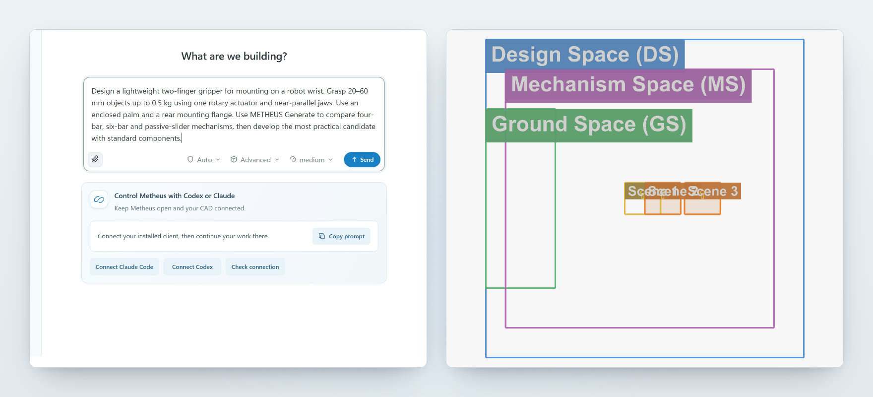
Target motion definition
We specified near-parallel finger motion to grip 20–60 mm objects weighing up to 0.5 kg with a single rotary actuator.
Space constraint definition
The mechanism had to fit inside an enclosed body. We reviewed mass, rear projection, and the moving envelope.
Other condition input
We compared four-bar, six-bar, and passive-slider options, prioritizing standard parts. Unspecified object pose, acceleration, and pad friction were recorded as assumptions.
In Design Problem Input, you can set every value precisely, and you can also edit values directly and easily in the CAD sketch.
02Autonomous Design
Mechanism generation
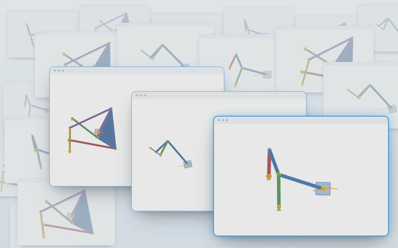
METHEUS generated 300 candidates across the three mechanism families; 167 passed a second check against the constraints.
Design review
The six-bar kept the fingers more parallel, but the four-bar was smaller, used fewer joints, and required less torque, so we selected it. We ruled out the passive slider because its finger angle varied too much.
3D modeling and part selection
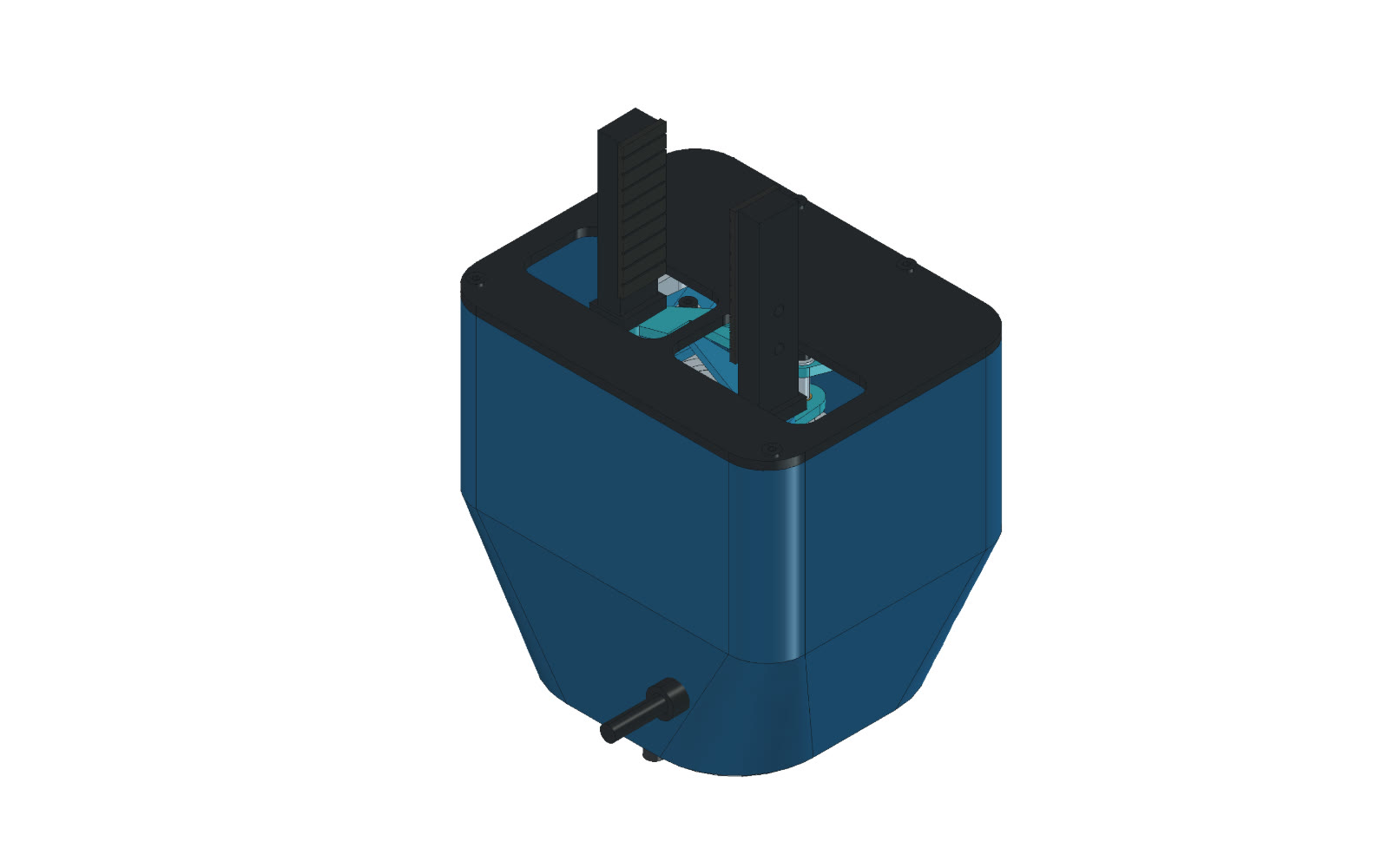
We modeled the fingers, links, and shafts of the four-bar design, then selected standard parts for a single actuator and four gears driving both fingers.
Part assembly and detailed design
In the same CAD file, we increased exposed finger length from 25 to 50 mm and added a rear adapter for the UR5e tool flange, preserving the mechanism and motion records.
BOM and drawings
We produced a 97-part BOM with 36 unique part numbers and review drawings. Estimated mass is 1.032 kg; FreeCAD and STEP files are available.
03Engineering Analysis and Reports
Analysis setup and execution
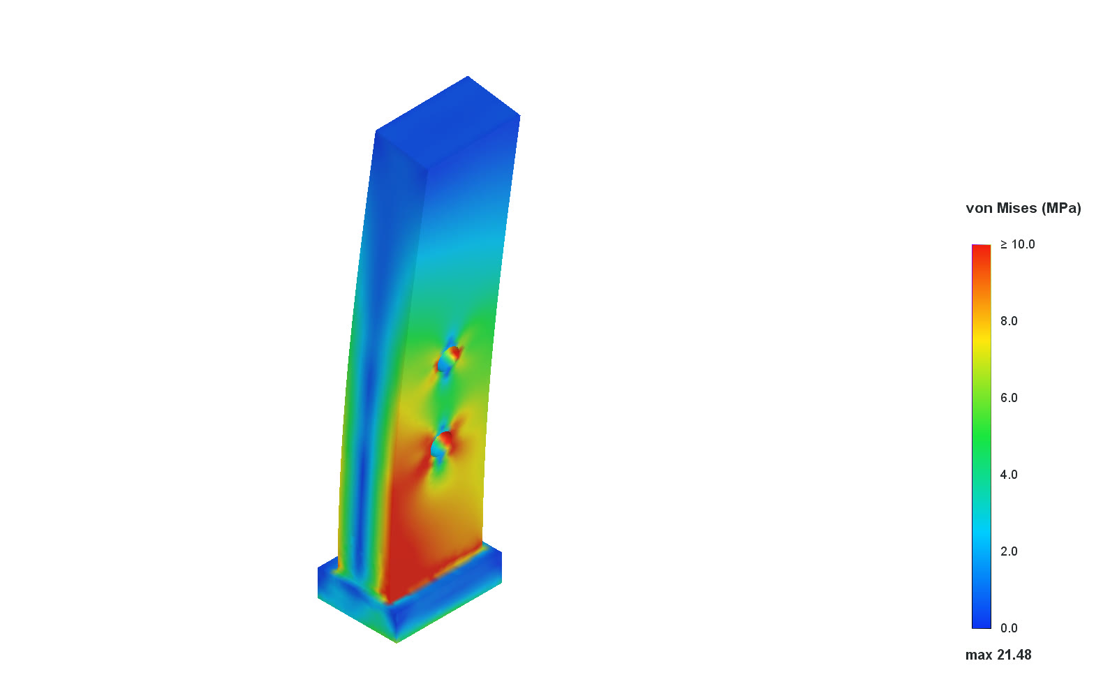
Static FEM on both fingers under 25 N normal and 7.405 N tangential loads showed peak stresses of 21.48/19.59 MPa and displacements of 0.052/0.039 mm.
Design report output
One design report brings together requirements, candidate selection, revisions, analysis results, and remaining checks for strength, fatigue, and slip.