Toggle Clamp Design
METHEUS took a manual toggle clamp from mechanism exploration through detailed design, motion analysis, and a design report.
- Design target
- Manual toggle clamp
- Target conditions
- Holding force 1.5 kN, clamping force 750 N, opening angle 100°
- Selected mechanism
- Four-bar RRRR rocker toggle from 600 generated candidates
- Deliverables
- Detailed 3D model, BOM, static and dynamic analysis, integrated report
01Design Problem Input
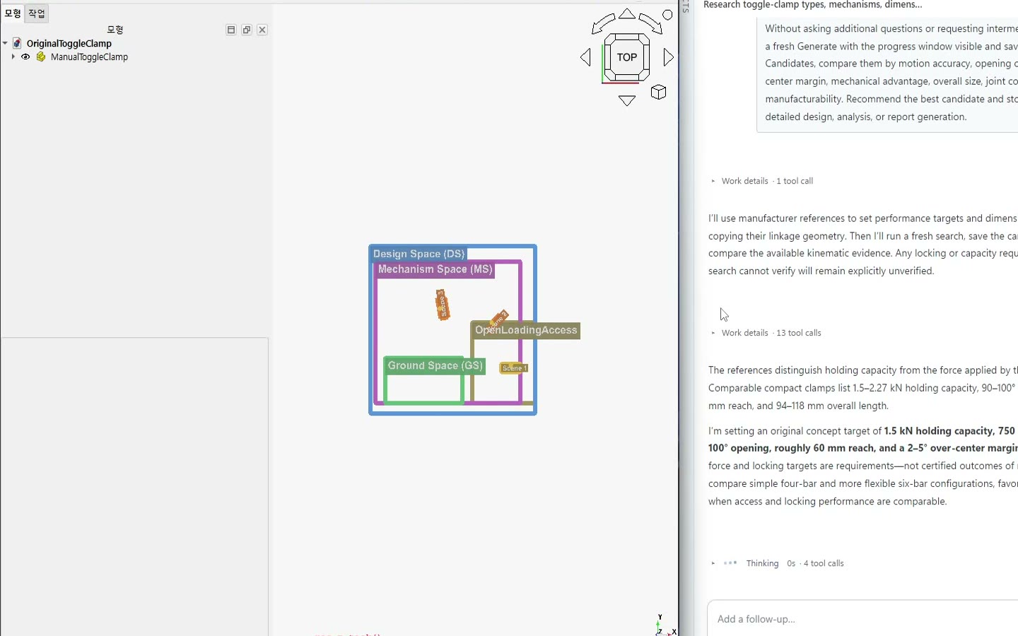
Target motion definition
We set a target handle opening of about 100°, moving from fully open to clamped and then past over-center to lock.
Space constraint definition
We reviewed room to load the workpiece, the motion path, size, and pad position.
Other condition input
We specified holding force, operator input force, and opening angle, then asked for linkages with different locking margins and mechanical advantage. We favored standard and readily fabricated parts.
In Design Problem Input, you can set every value precisely, and you can also edit values directly and easily in the CAD sketch.
02Autonomous Design
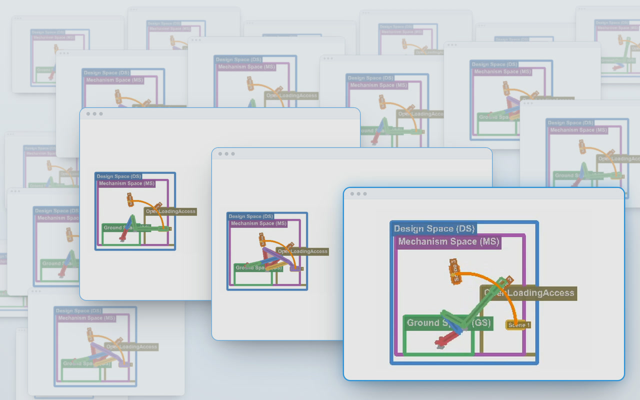
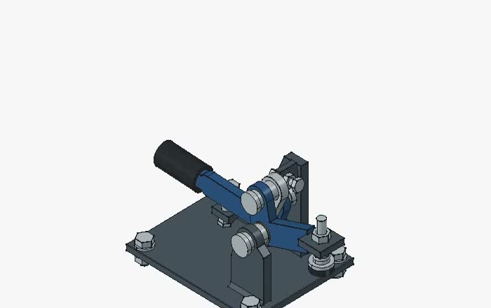
Mechanism generation
METHEUS generated linkages meeting the over-center lock and loading-space requirements. We compared motion accuracy, mechanical advantage, size, joint count, and manufacturability.
Design review
We compared motions from open to clamped and chose a candidate based on workpiece access, over-center behavior, and mechanism complexity.
3D modeling and part selection
We modeled links, the handle, pad, pins, and bushings, then selected materials and standard parts for the target holding and input forces.
Part assembly and detailed design
We reviewed clamping and release, corrected interference, pad alignment, and missing parts, then finalized the locking position, stopper, and assembly.
BOM and drawings
The BOM distinguishes purchased and fabricated parts. We documented the final CAD model and its clamping and release motion.
03Engineering Analysis and Reports
Analysis setup and execution
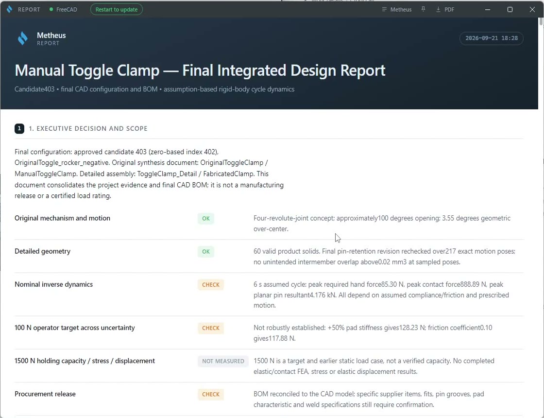
We reviewed forces and reactions at approach, dead center, and lock. Holding capacity, stress, and displacement still require verification.
Motion analysis and design report output
A full-cycle dynamics study under assumed conditions estimated forces, reactions, and the locking point. The design report also lists checks still needed.